Do you know about fuses??

DO YOU KNOW ABOUT FUSES??

Here present the article about the basic knowledge of fuses.


Fuse is perhaps the simplest and cheapest device used for interrupting an electrical circuit under short-circuit, or excessive overload, current magnitudes. As such,it is used for overload and/or short-circuit protection in high-voltage(upto 66 kV)and low-voltage(upto 400 V)installations circuits. In high-voltage circuits their use is confined to those applications where their performance characteristics are particularly suitable for current interruption. A action of a fuse is based upon the heating effect of the electric current.
In a normal operating conditions, when the current flowing through a circuit is with in safe limits, and heat developed in the fuse element carrying these current is readily dissipated into the surrounding air, and fuse element remains at a temperature below its melting point.

However,when some fault,such as short-circuit occurs or when load connected in a circuit exceeds its capacity,the current exceeds  then limit value,the heat generated due to this excessive current cannot be dissipated fast enough and the fusible element gets heated, melted and breaks the circuit. 
It thus protects a machine or apparatus  or an installation from damage due to excessive current. The time for blowing out of fuse depends upon the magnitude of the excessive current.Larger the current, the more rapidly the fuse will blow i.e.,the fuse has inverse time-current characteristic.
Such a characteristic is desirable for protective gear. Essentially,a fuse consists of a fusible element in the form of a metal conductor of specially selected small cross-sectional area,a case or cartridge to hold the fusible element,and In some cases provided with a means to aid arc extinction. The part is actually melts and opens the circuit is known as the fuse element. It forms a series part of the circuit to be protected against short- circuit or excessive overloads.

Fuse Element Materials:

This materials is used for fuse elements must be of low melting point,low ohmic loss,high
conductivity(or low resistivity),low cost and free from deterioration.Experience has shown that the most generally Suitable  material for the fuse element is a low melting point material such as tin,lead or zinc.
The present trend is to uses silver as fuse element material despite its higher cost.


Necessity of Fuse in an Electric Circuit:

If no fuse or other similar device is provided in the circuit then a dangerous situation would be created on developing of faults such as overload,short-circuit or earth faults.
In case of overload,short-circuit and heavy earth faults an  heavy current will continue to flow through the consuming apparatus, current carrying cables or wires and other current carrying equipment. Due to flow of heavy current through the cables or wires,apparatus etc.,these will get heated up and so damaged.The fire may also break out. In case of earth leakage fault,(i.e.on the body of the electrical apparatus becoming alive),the body of the electrical apparatus will continue to be alive and at much higher potential above that of the earth.In such circumstances any person coming in contact with the metal body of the apparatus is liable to get an electric shock,even if it is earthed.
The main function of a fuse is to blow out under a fault and isolate the faulty section from the live side.If the fuse is provided on neutral wire,in place of live wire,then in abnormal conditions though the fuse will blow out but the lamp or other apparatus still remains connected to the live wire and in case of leakage some trouble will arise and cause a considerable damage.In case the earth fault takes on the neutral wire between lamp and fuse provided in it,the fuse will blow out because the neutral wire is slightly at a higher potential with respect to earth and so the fault current flows through the neutral wire and fuse melts itself.The current will flow through the live wire,lamp,neutral wire and earth fault,even after the fuse has blown out and this may cause serious damage to the wiring,the apparatus connected or building itself.
If fuses of same capacity are provided on the phase wire and neutral,then in case of short-circuit fault,one of them will blow out first.If the fuse on neutral wire blows out first,
the fuse in phase line remains intact and faulty apparatus still remains connected to the live.If some person comes in contact
with the faulty apparatus,he is liable to get electric shock.In case the installation is connected to 3-phase 4-wire supply system and fuses are provided on both live and neutral wire and fuse on neutral  wire blown out then voltage of each phase to neutral will become considerably different which is not desirable. Hence the fuse is provided only in phase or live pole never on  neutral pole.

Fuses have following advantages and disadvantages.

Advantages.

  1. It is the cheapest form of protection available.
  2. It needs no maintenance.
  3. The operation is inherently completely automatic unlike a circuit breaker which requires an elaborate equipment for automatic action.
  4. The interrupts enormous short-circuit currents without noise,flame,gas or smoke.
  5. The min. time of operation can be made much smaller than the circuit breakers.
  6. The minimum sizes of fuse element impose a current limiting effect under short-circuit conditions.
  7. Its inverse time-current characteristic enables it use for overload protection.

Disadvantages.


  1. Its Considerable time is lost in rewiring or replacing a fuse after operation.
  2. On a  heavy short-circuits,discrimination between fuses in series cannot be obtained unless there is considerable differences in the relative sizes of the fuses concerned.
  3. The current-time characteristic of an fuse cannot always be correlated with that of the protected device.

The function of fuse wire is


  1. to carry the normal working current safely without heating and
  2. to break the circuit when the current exceeds the limiting current.

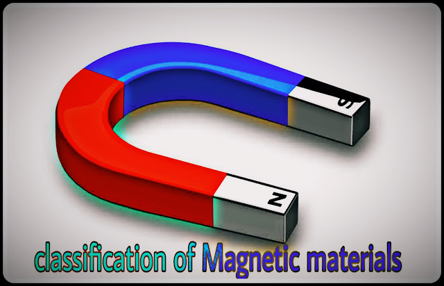
CLASSIFICATION OF MAGNETIC MATERIALS

CLASSIFICATION OF MAGNETIC MATERIALS

Although all materials have magnetic properties of some kind being either diamagnetic, paramagnetic or ferromagnetic, the term“magnetic material"is customarily applied only to substances which exhibit ferromagnetism.

1.Paramagnetic Materials:
The materials,which are not strongly attracted by a magnet,such as aluminium,tin,platinum, manganese etc.are known as paramagnetic materials. Their relative permeability is small but positive.For example,the relative permeability for aluminium,air and platinum are 1.00000065, 1.0000031 and 1.00036 respectively.Such materials are slightly magnetized when placed in a strong magnetic field and act in the direction of the magnetic field.
The paramagnetic materials the individual atomic dipoles are oriented in a random fashion. The resultant magnetic field is, therefore,negligible. When an external magnetic field is applied,the permanent magnetic dipoles orient themselves parallel to the applied magnetic field and give rise to a positive magnetization.Since the orientation
of the dipoles parallel to the applied magnetic field is not complete,the magnetization is small.These materials have little application in the field of electrical engineering.


2.Diamagnetic Materials:

The materials which are repelled by a magnet such as zinc,mercury,lead,sulphur, copper, silver, bismuth, wood etc. are known as diamagnetic materials.Their permeability is slightly less than unity.For example the relative permeabilities of bismuth,copper and
wood are 0.99983,0.999995 and 0.9999995 respectively.They are slightly magnetized when placed in a strong magnetic field
and act in a direction opposite to the applied magnetic field.
In diamagnetic materials,the two relatively weak magnetic fields(one caused due to orbital revolution and other due to axial rotation) are in opposite directions and cancel each other.Permanent magnetic dipoles are absent in them. Diamagnetic materials are unimportant from the point of views of application in the field of electrical engineering.


3.Ferromagnetic Materials:

The materials,which are strongly attracted by a magnet such as iron,steel,nickel,cobalt
and some of their alloys,are known as ferromagnetic materials.
Their permeability is very high(varying from several hundreds to many thousands).
The opposing magnetic effects of electron orbital motion and electron spin do not eliminate each other in an atom of Such a material.There is a relatively large contribution from each atom which aids in the establishment of an internal magnetic field,so.that when the material is placed in a magnetic  field,its value is increased many times the value that was present in the free space before the material was placed there.
For the purpose of electrical engineering it will suffice to classify the materials simply as non-ferromagnetic and ferromagnetic materials. The former includes materials of relative permeabilities practically equal to unity while the latter have relative permeabilities many times greater than unity. Paramagnetic and diamagnetic materials fall in the former(i.e. non-ferromagnetic)class.


Ferromagnetic materials are of two types:(a)those easily magnetized,called the soft magnetic materials and

(b)those retaining their magnetism with great tenacity,designated as hard magnetic materials.


(a)Soft Ferromagnetic Materials:
The  high relative permeability,low coercive force,easily magnetized and demagnetized and have extremely small hysteresis. Soft ferromagnetic materials are iron and its alloys with nickel, cobalt,tungsten and aluminium. Ease of magnetization and demagnetization  makes them highly suitable for applications involving changing magnetic flux as in electromagnets,electric motors, generators, transformers,inductors,telephone receivers, relays etc.They are also useful for magnetic screening.Their properties may be greatly enhanced through careful manufacture, and by heating and slow annealing so as to achieve a high degree of crystal purity.Large magnetic moment at room temperature makes soft ferromagnetic materials extremely useful for magnetic circuits but ferromagnetics are very good conductors and suffer energy loss from eddy currents produced within them.There is additional energy loss due to the fact that magnetization does not proceed smoothly but in minute jumps.This loss is called magnetic  residual loss and it depends purely on the frequency of the changing flux density and not on its magnitude.


(b)Hard Ferromagnetic Materials:
They have relatively low permeability,and very high coercive force.These are difficult to magnetize and demagnetize. Typical hard

ferromagnetic materials include cobalt steel and various ferromagnetic alloys of nickel, aluminium and cobalt.They retain high percentage of their magnetization and have
relatively high hysteresis loss.They are highly suited for use as permanent magnets in loud speakers etc.Sometimes they are also called the permanent magnetic materials.During
manufacturing, a  high degree of dislocation is introduced.Hard ferromagnetic materials are frequently heated to high temperature and then quenched in suitable liquid to introduce
strains.


4.Ferrites:
This is a special group of ferromagnetic materials that occupy an intermediate position between ferromagnetic and nonmagnetic materials.They consist of extremely fine particles of a ferromagnetic material possessing high permeability,and are held together with a binding resin.
The magnetization produced in the ferrites is.large enough to be of commercial value but their magnetic saturations are not as high as those of ferromagnetic materials.As in the case of terromagnetics,ferrites may be soft or hard ferrites.


(a)Soft Ferrites:
Ceramic Magnets,also called ferromagnetic ceramics and ferrites, are made of an iron oxide, Fe2O3, with one or more divalent 
Oxides such as NiO, MnO or ZnO. This magnets have a square histeresis loop and high Resistance to demagnetization.and are valued for magnets For Computing machines where a high resistance is desired. The great advantage of ferrites is their high resistivity. Commercial ferrites can have resistivities . Eddy currents resulting from alternating fields are therefore, reduced to a minimum, range of application of these magnetic materials is extended to high frequencies,even to microwaves. Ferrites are carefully made by mixing powdered oxides,
compacting and sintering at hightemperatures. High-frequency transformers in television and frequency modulated receivers are almost always made with ferrite cores.Ferrites,with large magnetostrictive effects,are sometimes used in electro- mechanical transducers.In high-frequency applications, magnetostriction in ferrites can lead to undesirable noise.


(b)Hard Ferrites:

These are ceramic permanent magnetic. materials.The most important family of hard ferrites has the basic composition MO.Fe2O3, where M is a barium (Ba) ion or a strontium (Sr)ion. These materials have a hexagonal structure and low in cost and density. A Hard ferrites are used in generators, relays and motors. Electronic applications include. the  magnets for loud speakers,telephone ringers and receivers. The also used in holding devices for door closers,seals,latches and in several toy designs. 
The separate class of magnetic material, known as super-paramagnetic, is made from powdered iron or other magnetic particles. This material is used in electronics and transformers for cores. The Permalloy (molybdenum- nickel-iron powder) is the best known example of this important category of magnetic materials.


Do you know about magnetism??

Here present the article about the what is magnetism and nature of magnetism

Megnetism


What is magnetism
What is magnetism

About twenty centuries before it was discovered that certain lead coloured stones possess a peculiar property of attracting fillings of small pieces of steel. Since this mineral was found in Magnesia(a province in Asia)in plenty,it was given a name of Magnetite. Magnetite(Fe3O4)is a magnetic oxide of iron and is found in large quantity in Sweden and North America.

Later on it was discovered that if an elongated piece of this mineral is suspended and made free to rotate in a horizontal plane, it would come to rest pointing north and south.The north seeking end of bar magnet is called its north(N-)pole, and the south seeking end its south(S-) pole.This mineral is  also called the lode stone meaning leading stone.

What is magnetism?
An Any body which possesses the power of attracting pieces of iron is known as a magnet and the property of a body by virtue of which this attraction takes place is known as magnetism.


Since lode stone possesses magnetism when it is taken out from the earth,it is called a natural magnet.Natural magnets are rugged and clumsy and also comparatively weak,therefore, have no practical utility.Commercial magnets are made artificially from iron and steel or alloy materials and are called artificial magnets.

Artificial magnets can be made either by rubbing a piece of iron or steel with the lode stone or by passing a heavy direct current through a coil wound over the piece of iron or steel.In the former method an iron or steel piece is magnetised by repeatedly rubbing a magnet over its entire length in the same direction. The piece converted into a magnet has its first terminal the same polarity and the last terminal has the opposite polarity to that of the end of the magnet used for rubbing.In the second method, which is more, common convenient, suitable and effective. direct current is passed in an insulated Copper coil wound round a piece of soft iron. Magnets prepared in this way are called electro- magnets.

Magnets employed in electrical machines and equipment aie of artificial type and generally horse shoe or U-shaped Because they can retain their magnetism for a very long time.
Magnets may be classified as being permanent or temporary,depending on their ability to retain magnetism.

Hardened steel and certain alloys of nickel and cobalt, when magnetised, retain their magnetism unaltered for long time after removal of magnetising force.Such substances are said to have high retentivity power and after being magnetized are termed as permanent magnets. Alnico is a widely used alloy (aluminium,nickel,cobalt,iron) for making permanent magnets. Permanent magnets are used extensively in telephone receivers,door latches,small DC motors, electrical measuring instruments, speedo-meters,and a great variety of gadgets.
Other substances,like soft iron are easily and strongly magnetized but lose most of their strength when the magnetizing force is removed.Such substances are said to have low retentivity power and termed as temporary magnet materials.These materials are of more importance than permanent magnet materials,both in total amount in use and in variety of applications.In electric generators and motors where it is desirable to control the amount of magnetism present in the magnet, soft  iron  temporary magnets are employed.

NATURE OF MAGNETISM

A Magnets have two opposite kinds of magnetism or magnetic poles,which attract or repel each other.One of the magnetic  poles is known as north pole and other as south pole. From experiments it has been observed that
(i) the Similar poles repel each other and opposite poles attract each other.
(ii)an Attractive or repulsive force between the two magnetic poles is directly proportional to the product of their pole strengths and inversely proportional to the square of the distance between them.
(iii) Molecules of all magnetic materials are complete magnets in themselves,each having north and south poles.If a bar magnet is broken into two parts. each part would be complete magnet in itself i.e.two new poles would appear at the breakage point. a new south pole on the piece which has the original north pole and a new north pole on the piece which has the original south pole. The subdivision of the bar magnet may be continued infinitely, but always with the same result,as illustrated . No process of division can produce an isolated single pole.If it were physically possible to break a magnet into so many pieces that each piece is a molecule,it would be logical to assume that each of these molecules would be a magnet.


Can you read more articles:
👇👇👇👇👇👇👇👇👇👇


Design of submersible motor

Here present the article about the design of submersible motor


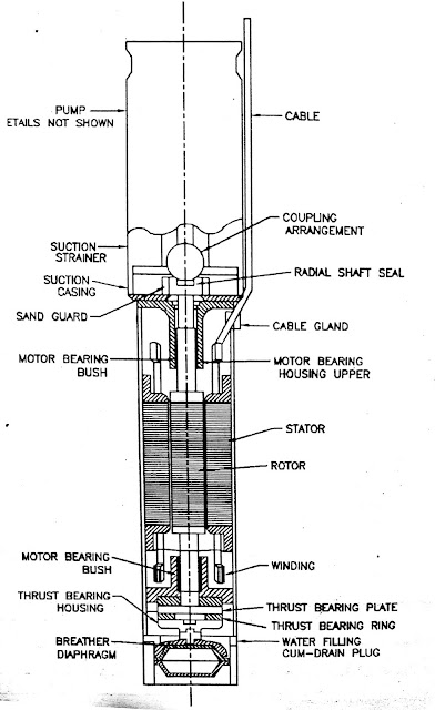
Submersible motor is used to drive the submersible pump.Submersible motor is also a squirrel cage type induction motor.Its principle and the general construction is similar to the squirrel cage type induction  motor.
It means there is laminated stator core and three phase winding in it and there is squirrel
cage rotor.But as the whole motor is under water,special type of construction has to be
employed. Mainly all the parts are made of the corrosion resistance type materials.Its diameter is less and the axial length is more. Instead or using the ordinary bearings the thrust bearings are used.

Types:
There are two types of construction of the submersible motor.

(1)Wet type submersible motor:
This type of motor is completely filled with clean water or oil or emulsion of water and oil.

(2) Dry type submersible motor:
In this type of motor the stator winding is dry and other parts are filled with clean water or oil or emulsion of water and oil.
Submersible motor
Submersible motor


Construction:
All the parts of the motor should be of corrosion resistance type and should posses the mechanical performance so that these are able to work continuously under water.

(a)Frame of motor:
Frame of the motor is made of cast iron. Casting should be strong and without crack.If necessary the pressure testing of the casting
should be done for crack detection.

Stator:
Stator is made of electric sheet steel.

(B) stator winding:
Stator winding is made of high conductivity annealed copper conductors insulated with PVC.
It should confirm to IS:8783-1978 and should be appropriate for wet type motor working
under water. For other type of submersible motor,the stator winding should be made of high conductivity annealed copper conductors and insulated with enamel.It should confirm to IS:4800(Part- VII) -1970. This standard shows specifications of round winding wires with good dielectric properties used in wet condition.

(c) Shaft and rotor:
Shaft is made of carbon steel.Rotor laminations are fitted on the shaft and copper bars are  embedded in the slots. There roads are short circuited at the two ends by copper short circuiting rings.Dynamic balancing of the rotor is done.Proper epoxy paint is applied on the rotor so that there is no corrosion of the rotor due to water.

(d)Bearings:
(1)Thrust bearings:Thrust bearing should be provided in the motor so that it can bear
the weight of all the rotating parts and the hydraulic thrusts produced in the operating
range.It should be properly lubricated. Housing of the thrust bearing is made of cast
iron and the bearing plate is made of bronze and the bearing ring is made of graphite.
Drain plug is provided in the thrust bearing so that oil or water filled in thrust bearing
housing or motor can be drained off.

(2) Radial bearing:Before installing the pump set,radial bearing of the rotary shaft should be lubricated with the clean water or oil.

Protection against external impurities: 
Motor should  be protected by using cable gland, rubber, seal etc.so that water of the bore well, sand and other impurities are prevented
from entering the motor.

Breathing attachment:Breathing attachment like bellow,diaphragm etc.should be used with motor so that the change in volume produced due to the change in temperature can be compensated.
Materials of different parts


Earthing:Earthing of the motor should be done as per IS:3034-1966.Earthing of the motor can also be done with the discharge pipe.

Submersible cable:Cable for submersible motor should be of PVC insulated PVC sheathed type and should confirm to IS:694-1977.Size of the inner conductor should be sufficient for the use in air and in water.
Consumer should specify the length of the cable required.If it is not specified,3 m length
of cable is provided with motor.If the cable joint is required the manufacturer-should provide the method of making water tight. joint Size and the length of the cable should be selected such that voltage drop up to the motor terminal should not exceed 3 %.

Ratings of motor:Voltage ratings of the submersible motor should confirm to IS:585-1962. Frequency should be equal to the standard frequency i.e.50 HZ.Change in the voltage and frequency for category A motor should be as per IS:325-1978 or as per IS:996-1979 and for category B motor should be as per IS:7538-1955.

(a) Preferred output ratings:Preferred output ratings should be as per IS:325-1978 or as per IS:996-1979.

(b) Speed ratings:Preferred synchronous speed is 1500 rpm or 3000 rpm.

(c) Rating plate:The following information is given on the name plate of the motor.

  1. Reference of Indian standards(IS 9283-1979) 
  2. Induction motor
  3. Name of the manufacturer
  4. Number of manufacturer and frame reference
  5. Type of duty
  6. Frequency in HZ.
  7. No.of phases
  8. Rated output in kW
  9. Rated voltage and winding connection
  10. Approximate current at rated output
  11. Speed in rpm at rated output
  12. Category of voltage and frequency variations.
  13. For convenient identification,number of manufacturer should be punched on the rating plate.

Basic knowledge of Inductor

Basic knowledge of Inductor

Here present the article about the basic knowledge of inductor


  • Inductor' is the passive electrical component used in electronic circuits that conserves the electrical energy from the current flowing through it as a magnetic field. '


What is inductor

In reality, a inductor is a wire. Which can be of any conductive material like: copper, aluminum, iron etc. When malformed material is placed around this wire. (This is called insulation.) And if it is wrapped round with no base or base, then this type of parts is called inductor. The insulation is applied so that the wire does not shorten when it is wrapped. The current is received from the end of the wire only from the other end and not in the middle.


Working concept of inductor

The electrical current flows through an wire conductor, the magnetic flux is developed around an conductor producing a relationship between the direction of this magnetic flux which is circulating around the conductor and the direction of the current flowing through the same conductor.This well known relationship between current and magnetic flux direction  is called "Fleming's Left Hand But the Rule”. But the other important property relating to the wound coil that also exists, that an secondary voltage is induced into the same coil by the movement of the magnetic flux as it is opposes or resists any changes in the electrical current flowing it.

 The basic form of ,an Inductor is nothing more than the coil of wire is wound around a central core.for the most coils a current (i) flow through the coil produces a magnetic flux,(N)around it that is proportional to the flow of electrical current. An Inductor,also called a choke,is another passive type of electrical component that is simply coil of wire that is designed to take advantage of this relationship by inducing a magnetic field in itself or in the core as result of the current passing through the coil.This results is more high the stronger magnetic field than one that would be produced by a simple coil of wire.

 Inductor are formed with wire tightly wrapped around a solid central core  which can either a straight cylindrical rod or a continuous loop or ring to concentrate their magnetic flux.

The symbol for a inductor is that of a coil of wire so therefore, the coil of wire can also be called as Inductor. Inductors are usually classified according to the type of inner core around which they are wound, for example, with different core types with hollow core (free air), solid iron core or soft ferrite core. Separated by adding continuous or dotted parallel lines. The Wire coil as shown below.


Inductor symbols
The current(i) flows through the inductor produces a magnetic flux that is proportional to it.But unlike an  Capacitor which oppose a change of voltage across their plates,a inductor opposes the rate of change of current flowing through it due to the creation of self-induced energy within its magnetic field.

In other words, the inductors oppose the changes of current but will easily pass a steady state DC current.This ability of a inductor to resist changes in current and which also relates current(i) with its magnetic flux linkage, NΦ  as a constant of proportionality is called Inductance which is given the symbol L with units of Henry,(H) after Sir Joseph Henry.

The according to Faraday's Law,any change in this magnetic flux linkage produces a self-induced voltage in the single coil of:


where:
N is the number of turns
A is the cross-sectional Area in m2
Φ is amount of flux in Webers
μ Is the Permeability of the core material
L the Length of the coil in meters-
di/dt is the Currents rate of change in amps/second

A time separating magnetic field induces a voltage that is proportional to the rate of change of current output and indicates an increase in EMF with a positive value and a decrease in EMF from a negative value. The equation, current and inductance related to this self-induced voltage can be found by replacing μN2A / 1 with L called the constant representation of proportionality called the inductance of the coil.
This relation between the flux in the inductor and the current flowing through the inductor is given as:Φ =Li.As a inductor consists of a
coil of conducting wire, then reduces the above equation to give the self-induced emf,sometimes called the back emf induced in the coil too:

Where:
L is self-inductance and di/dt the rate of current change.

Use of inductor

  • For making electrical filters 
  • For impedance matching 
  • To generate thousands of volts in the beginning for burning tubelight etc. and Two limit the current flowing through it after burning. 
  • create spark in old cars and scooters etc. (ignition coil)

Can you read more articles:
👇👇👇👇👇👇👇👇👇👇


What is Ohm's Law?
What is Ohm's Law

What is Ohm's law
What is Ohm's law

 A Ohm'  law is the relationship between the current I flowing through a resistance R and the potential drop across it V.

The current is directly proportional to the potential difference across the resistance and is inversely proportional to the resistance,
          I =V / R

As an alternative,Ohm's Law may be stated as:The potential difference V a resistance is directly proportional to the current I flowing
through the resistance and the resistance R,or
          V=I R

A Ohm's Law can be rearranged to define the resistance R so that
          R= V / I

If the potential difference across the resistance is measured in volts (V) and the current flowing through the resistance is measured in amperes then the resistance values will be in units of ohms.

Can you read more articles:
👇👇👇👇👇👇👇👇👇👇


Different types of the transformer

Basic knowledge of capacitor

Basic knowledge of capacitor

Here present the article about the basic knowledge of Capacitor.

Basic knowledge of capacitor


  • Capacitor is a passive element that stores energy in the form of electrical charge. Like a small rechargeable battery. 
  • The capacitor is a device whose use can increase the capacitance of the driver.
  • S.I unit of Capacitance is Faraday's  it is denoted by F. 
  • Capacitors are capable of storing charges. They are used for coupling AC signals from one circuit to another circuit and for frequency selection etc.
  •  An capacitor consists of 2 metallic plates separated by a dielectric.
The capacitance is defined as:
              C=ε0εr A/d,
      where A is the area of plates,
                   d is plates separation,
                       ε0 is permittivity of free space and 
                       εr is relative permittivity.
  • A important parameter for capacitors is its voltage handling capacity beyond which the capacitor dielectric breaks down.
  • The value of a capacitor depends upon the dielectric constant (K = ε0 εr) of the material.
  • Also capacitance is the change in electric charge with respect to time.
                C= dQ/dt


Circuit diagram of capacitor


there are three main classes of capacitors :
 (I) Non electrolytic or normal capacitors and
 (ii) electrolytic capacitor and
(iii) variable capacitor.

The Normal capacitors are mostly of parallel plate type and can have mica, paper, ceramic or polymer as dielectric. the paper capacitors two rectangular metal foils are interleaved between thin sheets of waxed paper and the whole system is rolled to form a compact structure.

each metal foil is connected to an electrode. in the mica capacitors alternate layers of mica and metal are clamped tightly together.

In the capacitor mostly a thin metal - oxide film is deposited by means of electrolysis on axial electrode. thats now it derives its name. during electrolysis the electrode acts as anode whose cathod is a concentric can.  the dielectric layer is very thin hence this require special precaution for their use: i.e.  they have to connected in the right polarity failing which the dielectric breaks down. besides this fixed value capacitors we also have variable capacitors whose value depends upon the area of cross section. they have an fixed set of plates and movement set of plates which can be moved through the shaft. this movement a changes the area of overlap of the two sets of plates which changes its capacity.


Series and parallel connections of capacitors:

Series Connection:


          1/C= 1/C1 + 1/C2 +....+ 1/Cn

Parallel Connection:


            C = C1 + C2 +...+ Cn