Design of submersible motor

Here present the article about the design of submersible motor


Submersible motor is used to drive the submersible pump.Submersible motor is also a squirrel cage type induction motor.Its principle and the general construction is similar to the squirrel cage type induction  motor.
It means there is laminated stator core and three phase winding in it and there is squirrel
cage rotor.But as the whole motor is under water,special type of construction has to be
employed. Mainly all the parts are made of the corrosion resistance type materials.Its diameter is less and the axial length is more. Instead or using the ordinary bearings the thrust bearings are used.

Types:
There are two types of construction of the submersible motor.

(1)Wet type submersible motor:
This type of motor is completely filled with clean water or oil or emulsion of water and oil.

(2) Dry type submersible motor:
In this type of motor the stator winding is dry and other parts are filled with clean water or oil or emulsion of water and oil.
Submersible motor
Submersible motor


Construction:
All the parts of the motor should be of corrosion resistance type and should posses the mechanical performance so that these are able to work continuously under water.

(a)Frame of motor:
Frame of the motor is made of cast iron. Casting should be strong and without crack.If necessary the pressure testing of the casting
should be done for crack detection.

Stator:
Stator is made of electric sheet steel.

(B) stator winding:
Stator winding is made of high conductivity annealed copper conductors insulated with PVC.
It should confirm to IS:8783-1978 and should be appropriate for wet type motor working
under water. For other type of submersible motor,the stator winding should be made of high conductivity annealed copper conductors and insulated with enamel.It should confirm to IS:4800(Part- VII) -1970. This standard shows specifications of round winding wires with good dielectric properties used in wet condition.

(c) Shaft and rotor:
Shaft is made of carbon steel.Rotor laminations are fitted on the shaft and copper bars are  embedded in the slots. There roads are short circuited at the two ends by copper short circuiting rings.Dynamic balancing of the rotor is done.Proper epoxy paint is applied on the rotor so that there is no corrosion of the rotor due to water.

(d)Bearings:
(1)Thrust bearings:Thrust bearing should be provided in the motor so that it can bear
the weight of all the rotating parts and the hydraulic thrusts produced in the operating
range.It should be properly lubricated. Housing of the thrust bearing is made of cast
iron and the bearing plate is made of bronze and the bearing ring is made of graphite.
Drain plug is provided in the thrust bearing so that oil or water filled in thrust bearing
housing or motor can be drained off.

(2) Radial bearing:Before installing the pump set,radial bearing of the rotary shaft should be lubricated with the clean water or oil.

Protection against external impurities: 
Motor should  be protected by using cable gland, rubber, seal etc.so that water of the bore well, sand and other impurities are prevented
from entering the motor.

Breathing attachment:Breathing attachment like bellow,diaphragm etc.should be used with motor so that the change in volume produced due to the change in temperature can be compensated.
Materials of different parts


Earthing:Earthing of the motor should be done as per IS:3034-1966.Earthing of the motor can also be done with the discharge pipe.

Submersible cable:Cable for submersible motor should be of PVC insulated PVC sheathed type and should confirm to IS:694-1977.Size of the inner conductor should be sufficient for the use in air and in water.
Consumer should specify the length of the cable required.If it is not specified,3 m length
of cable is provided with motor.If the cable joint is required the manufacturer-should provide the method of making water tight. joint Size and the length of the cable should be selected such that voltage drop up to the motor terminal should not exceed 3 %.

Ratings of motor:Voltage ratings of the submersible motor should confirm to IS:585-1962. Frequency should be equal to the standard frequency i.e.50 HZ.Change in the voltage and frequency for category A motor should be as per IS:325-1978 or as per IS:996-1979 and for category B motor should be as per IS:7538-1955.

(a) Preferred output ratings:Preferred output ratings should be as per IS:325-1978 or as per IS:996-1979.

(b) Speed ratings:Preferred synchronous speed is 1500 rpm or 3000 rpm.

(c) Rating plate:The following information is given on the name plate of the motor.

  1. Reference of Indian standards(IS 9283-1979) 
  2. Induction motor
  3. Name of the manufacturer
  4. Number of manufacturer and frame reference
  5. Type of duty
  6. Frequency in HZ.
  7. No.of phases
  8. Rated output in kW
  9. Rated voltage and winding connection
  10. Approximate current at rated output
  11. Speed in rpm at rated output
  12. Category of voltage and frequency variations.
  13. For convenient identification,number of manufacturer should be punched on the rating plate.
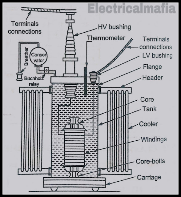
construction of 3 phase transformer

here present the article is knowledge about the construction of 3 phase transformer.


  • A three phase transformer has three primary windings and three secondary windings wound on a common magnetic core.
  • The core and the windings are enclosed in a tank filled with dielectric oil.
  • The terminals of the primary and secondary windings are connected to the interal end of the bushings.
  • The bushings provide the necessary insulation to the conductor.
  • The bushings are supported on the tank cover.
Accessories of transformers:
the various accessories used in the transformer are :
1. conservator tank 
2. high voltage and low voltage bushings
3. breather
4. Buchholz relay
5. tap changers

parts of distribution transformer
parts of Distribution transformer

1. conservator tank:

  • It is a large size cylindrical tank which is connected by pipe to the transformer.
  • The conservator tank is filled with transformer oil up to a certain level.
  • The remaining portion of the tank is filled with air.
  • Conservator oil is in communication with tank oil.
  • Expansion  contraction of transformer tank oil is accommodated by the air cushion in the conservator.The direct contact external air with oil is avoided.

2. high voltage bushings:


construction of 3 phase transformer
high voltage bushings


  • The function of high voltage bushings is to provide insulating  support to a conductor passing through earthen tank. 
  • Bushing comprises of a central conductor surrounded by graded insulation, A bushing is necessary when a conductor is taken out through a metallic tank,at earth potential. 
  • Porcelain bushing can be used up to 20 kV. Such a bushing consists of a single porcelain bushing,through which a single conductor is taken out.
  • Oil filled bushing is used for 33 kV applications.For 132 kV and above,oil impregnated paper condensor bushings are used.

3. breather:

construction of 3 phase transformer
Brether
  • the breather is filled with silica jel. the function of silica jel is to absorb moisture.
  • It is fitted between the air space of conservator and the outside vent.
  • The brething of transformers during load  takes place through breather.
  • When the load increases, the oil expands and the air from conservator is expelled.
  • During reduce load cycle,the oil in the conservator falls down and the atmospheric air is breathed in.
  • This incoming air is taken through the silica-jel.
  • Dry silica jel is of pale pink colour.It turns blue when it absorbs moisture.
  • The wet silica jel can be re-used after drying.

4. Buchholz relay :
construction of 3 phase transformer
buchholz relay

  • These relays are used for the protection of oil immersed transformers against all kinds of internal faults having rating more than 750 kVA.
  • It is a gas operated relay which is installed in the pipe connecting the conservator with the main tank.
  • Whenever any minor fault occurs,current leaks and heat is produced. Due to this heat,some oil evaporates in the transformer tank(about 70%hydrogen).
  • Since hydrogen gas is light,it tries to go into the conservator tank via relay.During the process, some gas and oil vapours are collected in the top chamber while passing to the conservator and the oil level in the tank falls.
  • The mercury type switch attached to the float is tilted, thereby closing the alarm circuit and the bell rings in the control room.
  • This gives a warning to the attendant,that some serious fault is going to occur inside the transformer.
  • When any severe fault takes place,larger volume of gas is generated in the main tank. These gases rush towards the conservator in a Buchhloz Relay resulting the tilting of mercury switch fitted on hinged type gap.
  • The trip coil contacts of the circuit breaker are closed.The pressure in the chamber can be released and the gas is emitted to refill with oil.A test cock is installed at the bottom of the chamber to allow air to be pumped into the chamber for test purpose.

5. Tap Changers:

construction of 3 phase transformer
Tap changer


  • Tap changer is fitted with the transformer for adjusting the secondary voltage.The adjustments in secondary voltage can be made by OFF circuit tap changer.Such adjustments are for seasonal load variations.
  • The tap is changed only after opening the circuit breaker on the supply side.Daily or short time voltage adjustment is made by means of ON load tap changer.
  • The tapping of ON-load tap changer can be changed without interruption in load current.
  • the modern practice is to install the tap changer within the transformer tank..
Different Types of the transformer

Different Types of the transformer

here present this article is khowledge about the Different types of the transformer

A transformer is a static electrical device which transfer a.c. electric power from one circuit to another circuit at the same frequency. 
From this definition,we can conclude that
  1. Transformer is a static electric device and do not have any rotating parts.
  2. It change electrical power starting with one circuit then onto the next circuit at a similar frequency at various voltage.
  3. It operate only with alternating current and do not function with D.C.supply.
there are two types of transformer:
1. core type transformer
2. shell type transformer

1. core type transformer:
core type transformer

  • In the core-type transformer,the magnetic circuit consists of two vertical sections called limbs with two horizontal sections, called yokes. 
  • The primary and secondary winding are provided on each limb.
  • The low voltage winding is kept inside near the core,while the high voltage winding is placed on it.
  • This type of winding arrangement in the core type transformer provides magnetic coupling between primary and secondary winding.
  • Thus,the two windings are arranged as concentric coils such a windings is therefore,called concentric winding.
  • in most of the core type transformers circular cylindrical coils are used because of their mechanical strength , while placing these coils an insulation layer is provided between core and lower coil and also between the two coils.
  • it should be noted that low voltage winding is wound near the core since it is easiest to insulate.if the high voltage winding is wound near the core a heavy insulation will have to be prvided to avoid earth leakage.
core type transformer

advantages :
  1. natural cooling is more effective.
  2. construction is simple.
  3. the coils can be easily withdrawn for repair.
2. shell- Type transformer :
shell- Type transformer
  • in the shell- type transformer both primary and secondary winding are wound on the central limb and the two outer limbs complete the low reluctance flux paths.
  • winding are normally of sandwich type.
  • the top and bottom coils, which are near the yoke of the core, are of L.V. winding only.
advantages :
  1. better mechanical protection to the winding.
disadvantages :
  1. natural cooling is poor.
  2. the coils can be easily withdrawn for repair.
Distribution transformer :
distribution transformer
  • Transformer upto 500 kVA are used to step down distribution voltage to a standard service voltage or from transmission voltage to distribution voltage are known as distribution transformers.
  • They are kept running all 24 hours a day, regardless of whether or not they carry loads.  The load on the distribution transformer varies from time to time and the transformer will remain empty for most of the time.
  • Therefore in the distribution transformer the loss of copper (which depends on the load) will be greater than the loss of the core (which occurs until the transformer is in operation).
  • So the distribution transformers are designed with less iron loss and designed to have maximum efficiency at a much lower load than full load.
  • it should have a good regulation to maintain the variation of the supply voltage with limits and therefore it is designed with a reduced value of the dispersion reactance.

power transformer :
power transformer
power transformer

  • The transformers used in sub-stations and generating stations are called power transformers.
  • They have ratings above 500 kVA.Usually a substation will have number of transformers working in parallel.
  • During heavy load periods all the transformers are put in operation and during light load periods some transformers are disconnected.
  • The power transformer is designed to have a leakage response greater than the permissibility in the distribution transformer to limit the fault fault.
  • In the case of power transformers, inherent voltage regulation is less important than the current limiting effect of high leakage response.
Basic principle of Electrical transformer

here present the khowledge about the article is basic principle of Electrical transformer

what is transformer?
A transformer is a device that transfers electrical energy from one circuit to another circuit through a magnetic field and without any change in frequency.

In this, the electric circuit that receives the electrical power of the source is called primary winding and the second circuit which delivers electric energy is called load secondary winding.
Definition:  If we look at the definition of Transformer above then we will find that it is a device that either step-up the voltage or step-down, that is also according to the corresponding decrease and increase of current.
  • The transformer is actually an electromagnetic energy conversion device, in which the energy that is received is first converted into primary winding into magnetic energy and then it is reconverted again to secondary winding in electric energy.
  • It is important to understand that transformers do not generate electrical power.
  • They electrical power transfer from one AC circuit to another circuit using magnetic coupling.
  • The core of the transformer is used to provide a controlled path to the magnetic flux that is generated by the current in the transformer that flows through the windings, also called coils.


Who invented the transformer

 Electric transformers were invented by William Stanley in 1885 in the United States.  And it is also said that the transformer was invented by Michael Faraday in 1831 in Britain.


On what principle does the transformer operate?

  •  If we talk about transformer, then the principle on which it works is called Faraday's Law of Electromagnetic Induction.
  • this Principle is say that, "The magnitude of voltage is directly proportional to the rate of change of flux."

 Now let us know about Transformer's Parts.


  •  Although transformers have many parts but the most prominent of them are three parts,

  1.  Primary Winding of Transformer
  2. Transformer's Magnetic Core
  3. Secondary Winding of Transformer

 1.  Primary winding
This is the primary winding that produces magnetic flux when it is connected to an electric source.

 2. Magnetic core

The magnetic flux generated in this primary winding is passed through a low reluctance path which is linked to secondary winding and it creates a closed magnetic circuit.

3. Secondary winding

 The flux that occurs in the primary winding is passed through the core which is linked with the secondary winding.  This winding is also wrapped in the same core and it also produces the required output of the transformer.
working principle of transformation
working principle of transformer

Working principle of transformer

  • The working principle of the transformer is very simple.  Mutual induction is used in between two or more windings that allow electrical energy to be transferred between these circuits.
  • Suppose you have a winding and an alternating electrical source supplied to it.  Now this alternating current that is flowing through this winding generates an constantly changing and alternating flux that surrounds the winding.
  • Now if a second winding is brought closer to this winding, then some part of the alternation flux will link with the second winding.  Since this flux is constantly changing in its amplitude and direction, a changing flux linkage is attached to the second winding or coil.
  • According to Faraday Law of Electromagnetic Induction, an EMF is born in Secondary Winding.  Whereas if the circuit of secondary winding is closed then current flows in it.  This is the basic principle of transformer working.
  • The thing to understand in this is that the winding in which electric power is received from the source is called primary winding.  Whereas the winding from which you get the desired output voltage is called 'secondary winding' due to mutual induction.

What are step-up transformers?
  • A transformer that increases the voltage between the primary to secondary windings is called a step-up transformer.

 What are step-down transformers?
  • At the same time, a transformer that reduces the voltage between the primary to secondary windings is called a step-down transformer.

 Why is the transformer called a Static Device?

  •  No moving part is required to transfer electric energy from one circuit to another in the transformer.  This is the reason that they are called a Static Device.


Application of electrical transformer

  1.  Refrigerators, radio, telephone and T.V. transformers are used in our daily lives.
  2.  Welding in factories and transformers are used in various types of furnaces.
  3. Where electric power is produced, the power of current is sent to our homes by reducing the transformer.
  4.  Distribution transformers are used to distribute current
What is Induction Generator
here present the artice about the inducion generator and principal of operation and advantages and application of induction generator

👉Induction Generator

defination :when the slip of the induction motor is less than zero, i.e. when the induction motor runs above the synchronous a speed then it runs as a generator called induction generator.

  • the negetive slip indicates that the rotor of induction motor is running faster than synchronous speed. 
  • hence to run the induction machine as an induction generator, its slip must be negative 

  • show the induction generator which is driven by the prime mover such as engine or wind turbine and is comnected to a 3-phase load.
  • when the speed of induction generator is above its synchronous speed the active power(p) is delivered by the generator to the 3-phase load and the corresponding mode of operation to the induction machine is called generating mode and the slip of induction machine will be negative.
  • however for creating its own magnetic field, it absorbs reactive power(Q) from the 3- phase line or capacitor bank.

touque - speed characteristics


  • the touque- speed characteristics for motoring and generating mode of induction machine is show in figure.
  • the construction of induction generator is the same as that of induction motor.
  • the only difference in case of induction generator is that the direction of rotation or induced torque is reversed.

principle of operation

  • when the 3- phase induction motor is driven at a speed greater than synchronous speed by an external prime mover with exciting current provided either from 3- phase line or capacitor bank, the emf and current of slip frequency will appear in the rotor winding. but the direction of this emf and current will be opposite, as compared to the direction when it is operating below the synchronous speed.
  • In generating mode of operation,an external prime mover drives the rotor above the synchronous speed.The stator flux induces currents in the rotor,but since the opposing rotor flux in now cutting the stator coils,an active current is produced in stator coils and the motor operates as a generator,sending power back to the grid.

Advantages of induction generator

  1. they are mechanically and electrically simpler than other type of generators.
  2. simple robust and rugged in construction.
  3. relatively cheaper.
  4. Requires no brushes and commutator.
  5. Easy in maintenance.
  6. they do not have to be synchronised to the supply lines as does a synchronous generator.

Applications of induction generator

  • Iduction generator are often used in wind turbines and small hydro power station due to their ability to produce usefull power at varying rotor speeds.
  • induction generators are particulary suitable for wind generating station as in this case speed is always a variable factor.
  • they are also very useful in automatic dynamic braking such as for braking purposes in case of railways.
classification of ac motors

Here present the knowledge about the definition of ac motors and classification of ac motors. And working principle


Defination: Ac motor is an electric motor that is driven by alternating current. The basic principle of AC motor is convert electrical energy into machanical energy.

➡Ac motors can be classified on the basis of following:
Based on their principle of operation
 (A) synchronous motors:-
  • synchronous motor is an ac motor which converts electrical energy into mechanical energy while rotating at a constant speed equal to synchronous speed.
  • Synchronous motors are constant speed motors.
  • They operate in synchronism with the line frequency and are commonly used where precise constant is required.
(B) asynchronous motors:-
  • The asynchronous motor is an ac motor in which the rotor rotates at a speed slightly less than the synchronous speed.
  • An induction motor is also called asynchronous motor as it does not run at synchronous speed.
  • There are two type of asynchronous motor.
         (A) induction motor
                (1) squirrel cage type
                (2) slip - ring or wound rotor
         (B) commutator motors

based on the nature of current
      (1) single phase
      (2)  three  phase
based on their speed
      (1) constant speed 
      (2) variable speed
      (3) adjustable speed

⏹Working principle:

  • The basic principle of induction motor is to power takes place in the rotating part of the motor.
  • In induction motor there is no electrical connection to the rotor i.e. no supply is given to rotor from any external source of supply, but the current which includes in the rotor conductors is by the relative motion of the rotor conductors and the stator rotating magnetic field.
  • The rotor does not receive electric power by conduction but by induction.That is why this AC motor is called an induction motor
  • The three phase induction motor operates on the principle of mutual induction.When the 3-Phase stator winding of a three phase induction motor is supplied by a 3-Phase AC supply, a rotating magnetic field of constant magnitude is set up,which rotates at constant speed equal to synchronous speed.
  • This rotating flux cuts the stationary rotor conductors and induces e.m.f. in them by mutual induction. 
  • Due to the relative speed between the rotating magnetic field of the stator and the stationary rotor conductors, an e.m.f. is induced in the rotor conductors.
  • This e.m.f.causes the heavy circulating current to flow due to very small resistance of the rotor and also the rotor circuit is closed. 
  • The frequency of the induced e.m.f. or current at the time of starting is equal to the supply frequency. 
  • The rotor induced current,according to Lenz's law flows in such a direction that it opposes the cause, which is inducing the current.In three phase induction motor,the cause producing the currents in the rotor is the relative speed between the rotating magnetic field of stator and the stationary rotor conductors.